Specification

- Processors
- two Socket 370 connectors for Intel Pentium III, 500-1000 MHz and higher
- FSB 100/133 MHz support
- Chipset
- VIA Apollo Pro 133A: 694XDP + VT82C686B
- RAM
- 4 168-pin unbuffered DIMMs with support up to 8 memory banks
- 4.0 GBytes max memory size
- ECC(1-bit Error Code Correct) support
- VC SDRAM, HSDRAM support
- Expansion slots
- 1 AGP 4x / AGP Pro slot
- 5 PCI slots, Bus Master and 3.3V/5V interface PCI bus support
- On-Board IDE
- 2 IDE channels on the VIA(R) VT82C686B chip, support for all modes up to Ultra DMA 100
- Sound
- Sound Blaster / Direct Sound AC97 Audio optionally in the VT82C686B chip
- Integrated I/O ports
- 1 port for FDD (360K, 720K, 1.2M, 1.44M, 2.88M)
- 2 serial ports
- 1 parallel port with SPP/EPP/ECP support
- 4 USB ports
- 1 IrDA port (compatible without the second serial port)
- SCSI
- two-channel Ultra160 SCSI controller
- LSI 53C1010-33 chip
- 2 68-pin connectors, up to 30 devices totally
- LAN
- 10/100BaseTX netcard
- Intel 82559 chip
- Hardware Monitoring
- temperature control of two processors and motherboard
- 3 fans' speed control
- 5 voltages control
- connection of the case opening sensor
- BIOS
- Award 6.0 BIOS
- Plug&Play, DMI, AMP, ACPI
- JumperFree (tm) CPU frequency choice
- AGP - AGPx4, AGP Fast Write settings
- WOT, WOL, WOM
- Dimensions:
- ATX Form Factor, 26 cm x 30.5 cm

The board is shipped in a beautiful dark blue box. Apart from the board, a user's manual, and a CD with drivers the complete set includes the following cables:
- 40-pin IDE, 34-pin FDD
- 80-pin UDMA66/100
- 68-pin UltraWide SCSI with three internal and one external connectors
- 68-pin Ultra160 SCSI with a terminator, for 5 devices
Besides, there is a bracket with a cable for two additional USB ports and a bracket for the ATX case.

A CPU terminator is mounted into the second socket.
Beside the drivers for the chipset, the netcard and the SCSI adapter the CD includes: AcrobatReader 4.0, ASUS HotKey, Intel LDCM 6.1, Trend PC-cillin OEM Ver 4.02, CyberLink PowerDVD 2.55 and PowerPlayer SE, ASUS PC Probe, VideoLive Mail 3.1.
Installation
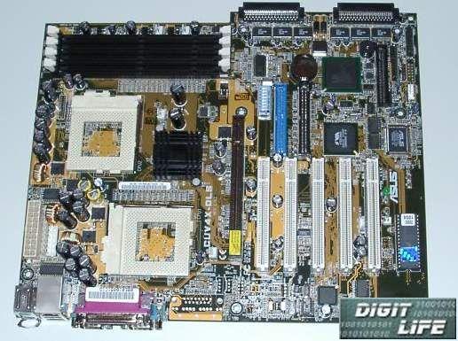
The board is a bit bigger than a standard ATX size due to the jut with SCSI connectors. But it doesn't hinder installation in any standard case. The layout is rather compact due to two sockets, SCSI and network controller.
The monitoring of the board and processors' status is provided by the ASUS proprietary chip. It controls processors' temperatures via the sensors integrated on them, and motherboard' temp via a sensor mounted on it. There is no possibility for connection of one more thermistor. There are 4 connectors for fans but only three are controlled. You can enable a "fan off" mode when the system is in the "sleep" mode. A LED located in the below part of the board serves an indicator of voltage supply on the board.
There is nothing to prevent an installation of processors and coolers. You can even mount a couple of the Thermaltake Golden Orbs. 4 SDRAM DIMMs are located in a usual place. Even a usage of a long AGP video card does prevent their access.
IDE connectors are located in the center of the board. I think that the FDD port's position is the worst - its cable goes over IDE connectors and the memory.
Since SCSI connectors are located "in parallel" to the board, the connector's cable can go either up or down. In the second case it makes no good - you have to bent the cable strongly, especially for such high speeds as 160 MBytes/sec. The U160 cable included in the set is "wrong", and the UW one is "right".
The board includes only 5 PCI slots that's why the lowest slot can be used for the bracket for two additional USB ports.
The chipset is equipped with a small heatsink (without glue), but it didn't heat much during the tests. The clock generator chip rises much more anxiety. At low FSB (more than 140MHz) its temperature reached 50 degrees C!
Since the internal audio connectors are located right under the video card it may cause troubles for a variant with AC97 sound.
The board features its own speaker, that's why it's not necessary to use case's speaker.
The ATX power supply connector is located near the upper edge of the board and it can be difficult to reach in some cases. Besides the standard ATX power supply the board has an additional connector for 3.3 and 5 V in case of heavy-loaded configurations.
An integrated network controller can be disabled with a jumper on the board. The RJ45 controller is located above the USB ports. Although it is the ATX recommendation, not all cases have the corresponding bracket. For such cases ASUS offers its own one. There is a couple of LEDs near the connector. When on the net the green LED works as a link/act indicator. The second, an orange one, shows that the card is connected to the 100 Mbit network.
You can enable Intel Boot Agent support via BIOS SETUP, it will allow to boot the PC via the network with usage of PXE and RPL protocols. Despite the fact that the board supports WOL it doesn't work with the integrated network adapter. And in case of usage of the external netcard and WOL connector on the board everything awakes excellently.
The two-channel SCSI controller on the LSI 53C1010-33 chip allows connecting up to 30 devices. Two SCSI channels act as separate controllers, they even use separate interrupt lines. SCSI BIOS has a plenty of settings, including a choice of the booting order from SCSI devices, switching them on and scanning during booting, limitation of the max speed for each devices etc. Besides, it supports booting from the CD. BIOS SETUP contains also several settings concerning SCSI controller: SCSI BIOS enabling, terminators' enabling. Besides, there is a possibility to set a booting order from the controllers - an integrated or an external ones. The controller may be switched off with a jumper on the board. The only problem of the integrated SCSI controller is the lack of 50 pin (narrow) SCSI connector. It means that you have to use an adapter for connecting CD-ROM, CD-RW, scanner etc.
Interrupt lines on the CUV4X-DLS are distributed the following way:
 | AGP | PCI 1 | PCI 2 | PCI 3 | PCI 4 | PCI 5 | USB | LAN | SCSI 1 | SCSI 2 | Audio |
| INT A | * | * | | | | | | | | * | |
| INT B | | | * | | | | | * | | | * |
| INT C | | | | * | | | * | | | | |
| INT D | | | | | * | * | | | * | | |
Overclocking
The CUV4X-DLS manufacturer has realized only a possibility to change FSB frequency (and a multiplier for unlocked processor). You can't rise the Vcore and Vio. There are 16 FSB speeds which can be chosen with the jumpers on the board. But the JumperFree technology offers much more possibilities which allows to choose all parameters in the BIOS. In this case for the CUV4X-DLS board the following frequencies can be chosen:
| FSB | PCI | AGP | FSB/PCI | MEMCLK |
66.9 | 33.45 | 66.90 | 2 | - | 66.9 | 100.4 |
68.0 | 34.01 | 68.02 | 2 | - | 68.0 | 102.0 |
75.0 | 37.50 | 75.00 | 2 | - | 75.0 | 112.5 |
80.0 | 40.00 | 80.00 | 2 | - | 80.0 | 120.0 |
83.3 | 41.65 | 83.30 | 2 | - | 83.3 | 125.0 |
85.0 | 28.34 | 56.68 | 3 | 56.7 | 85.0 | 113.3 |
90.0 | 30.00 | 60.00 | 3 | 60.0 | 90.0 | 120.0 |
95.0 | 31.67 | 63.34 | 3 | 63.3 | 95.0 | 126.7 |
100.2 | 33.41 | 66.82 | 3 | 66.8 | 100.2 | 133.6 |
103.0 | 34.33 | 68.66 | 3 | 68.7 | 103.0 | 137.3 |
105.0 | 35.00 | 70.00 | 3 | 70.0 | 105.0 | 140.0 |
110.0 | 36.66 | 73.32 | 3 | 73.3 | 110.0 | 146.7 |
112.0 | 37.34 | 74.68 | 3 | 74.7 | 112.0 | 149.3 |
115.0 | 38.33 | 76.66 | 3 | 76.7 | 115.0 | 153.3 |
116.0 | 38.66 | 77.32 | 3 | 77.3 | 116.0 | 154.7 |
118.0 | 39.33 | 78.66 | 3 | 78.7 | 118.0 | 157.3 |
120.0 | 40.00 | 80.00 | 3 | 80.0 | 120.0 | 160.0 |
124.0 | 31.00 | 62.00 | 4 | 93.0 | 124.0 | - |
126.0 | 31.50 | 63.00 | 4 | 94.5 | 126.0 | - |
130.0 | 32.50 | 65.00 | 4 | 97.5 | 130.0 | - |
133.0 | 33.25 | 66.50 | 4 | 99.8 | 133.0 | - |
135.0 | 33.75 | 67.50 | 4 | 101.3 | 135.0 | - |
138.0 | 34.50 | 69.00 | 4 | 103.5 | 138.0 | - |
140.0 | 35.00 | 70.00 | 4 | 105.0 | 140.0 | - |
142.0 | 35.50 | 71.00 | 4 | 106.5 | 142.0 | - |
144.0 | 36.00 | 72.00 | 4 | 108.0 | 144.0 | - |
146.0 | 36.50 | 73.00 | 4 | 109.5 | 146.0 | - |
148.0 | 37.00 | 74.00 | 4 | 111.0 | 148.0 | - |
150.0 | 37.50 | 75.00 | 4 | 112.5 | 150.0 | - |
155.0 | 38.75 | 77.50 | 4 | 116.3 | 155.0 | - |
160.0 | 40.00 | 80.00 | 4 | 120.0 | 160.0 | - |
166.0 | 41.50 | 83.00 | 4 | 124.5 | 166.0 | - |
We managed to get the system with two processors work at FSB 144 MHz. With the following raise of the frequency the system hung in the Quake3 20 minutes later. For ASUS it's undoubtedly weak result.
There were no claims for reliability. During the test the system has never booted, the Stress Tests were started up together with several video and netcards under Windows2000 Pro and Windows NT Server.